In my current role, I am spending more time, by necessity, in Visio to help define and visualize system architectures and system integrations. There was one thing that always bugged me about Visio that I never really figured out. The issue I was having was when you had multiple connections coming into the same object they all overlapped. This always seemed like a shortcoming that almost every default object only four connection points. As I have been building more diagrams recently this became a bigger problem and more of an annoyance.
Now if you are a Visio expert maybe this is already something you know how to do. However, I did not, so I am assuming this is some person out there I will help out. Because, when I found the solution, I was floored
My first attempt to solve the problem was just to not use the connection points. Every time I needed a connection, I would instead create a line that would just hover away from the object it was pointing to.

Figure 1 – Adding a Line Object
That resulted in something that looked like this:

Figure 2 – Adding Multiple lines to an Object
That worked okay for a little while, but definitely had some drawbacks. The main one was that if I needed to move something then I also needed to move all my arrows. Some of the aspects of drawing the arrows was a little suboptimal as well. So I needed to find another option.
My next line of thinking was that I would have to create my own object. I have tried this in the past a couple times for other reasons and failed miserably so I was reluctant to go down this path. So, I decided to turn to the internet as all good people do these days.
Lo and behold it turns out that there is a super cool feature of Visio that I either never saw or have been ignoring my whole life. I have no idea which one of those is correct, though I am guessing that I probably have just been ignoring it my whole life. It turns out that you can explicitly add a connector to an existing object.

So, how does this cool feature work?
On the Home Tab, in the Tools section click the Connection Points icon which is an “x”.

Figure 3 – Change to adding Connection Points
Now to add a connection point to an object just hold the Ctrl button and click the object where you would like to have the connection point added. Here is an example after I have added some new connection points on the right hand side of the object. Note, I found this easier to when I was zoomed into the object > 100%.

Figure 4 – Adding Connectors on the Right Hand side.
Now after I have added a whole bunch more connectors. I am not restricted to adding them to just the outside edge of the object either. I can add them inside the object and also outside the object. So if I want to have the end of the connector hover outside the object, that is possible.

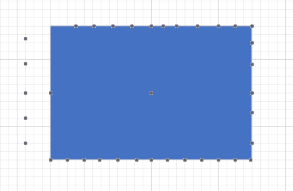
Figure 5 – Object with a bunch of connectors
So now, adding connectors into the object is super easy and flexible and it gives me a much better visualization in my diagram.

Figure 6 – Connectors connecting to Connection Points
So, now because I am using connectors instead of lines, everything moves then I move object and I get all the other benefits that come with using connectors vs. lines. Contrast that with what it would look like if I had only used the standard connectors on the object

Figure 7 – Multiple Lines with only Standard Connectors
Now, there might be situations where having all the arrows coming into a single connection point makes sense from a visualization to show multiple inputs coming together in a single line. In my scenario representing the distinct arrows made sense. If it makes sense for your diagram now you have a easy way to do it. If you find that you want to save this as your own object it might make sense to move into your custom stencil.
Happy Diagramming!

Nice one Andrew – that was really helpful. Thanks heaps.
LikeLike